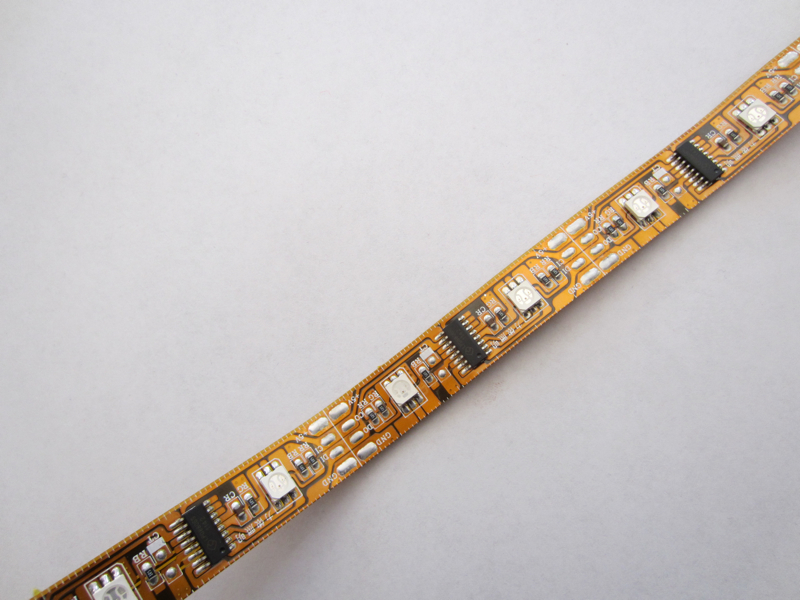
In my continuing quest
to use up the 15' of RGB LED ribbon
(LPD8806) I purchased from AdaFruit,
it occurred to me that I could use a short segment of the ribbon (10
LEDs worth) to build a light for our kitchen table in our new home. I
discussed the idea with my wife and she was, shall we say, slightly
skeptical that
1. A weird shaped blinky thing was the right light for over our kitchen table in our new home
2. A weird shape blinky thing would be bright enough to have dinner by
3. Any one would want to eat dinner with a light show going on over head.
All good points I must concede. Undaunted, as we men typically are, I decided that the only way to find out if a blinky kitchen table light would work was to build one. The rest as they say is history.
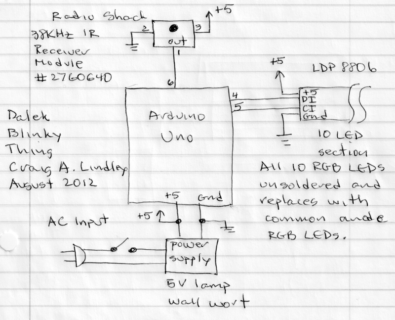
I had an Arduino Uno on hand so I decided to use it to drive the LEDs in the light. I had numerous display patterns in mind so I needed to be able to control the light remotely as I didn't want to climb a ladder to change modes manually. I first designed the hardware (see schematic below) then wrote the software which is available here. My software uses Ken Shirriff excellent IRremote library available from github at http://github.com/shirriff/Arduino-IRremote. Thanks Ken, you made my job much easier.
Finally I turned my attention to what the light should look like. I thought about what shape I should make the light and how many LEDs would be needed to provide sufficient illumination. I wanted something modern looking but at the same time kind of craftsman style to fit in with our other furniture. I decided on a triangle shaped light that would hang on a cord from the ceiling. That meant the light would have to connect to 115 VAC as that is what the ceiling fixture provides. This also meant the light had to have a built in 5V power supply to run the Arduino, LED strip and the IR receiver. It was important that when the wall switch was flipped on the light would come on as quickly as possible and go into a bright white display mode so it acted like a "normal" light.
Remote Control
I wanted to use a small remote to control the light. I looked through my stash and found the remote that was used for our Roku streaming device. It was small but had enough buttons for my use. NOTE: if you use my software with a different remote you will have to change the code slightly. See the code listing for the details.
The Dalek light operates in three distinct modes.
1. Manual display select mode where the remote is used to select the speed and a specific display pattern for the light to display. The selected pattern and speed will continue indefinitely until changed.
2. Static color mode where the remote is used to select the color or hue for the light to display and to control the brightness of the display. All LEDs assume the selected hue and brightness.
3. Random display mode where the light picks the display speed and the pattern randomly. Each display pattern is displayed for 60 seconds when a new pattern and speed are selected and displayed. This results in an almost infinite number of display patterns.

One pleasant but
unanticipated side effect of the light's packaging is that in the dark
the light projects a collage of colors on
the wall behind it. The color and the projected shapes change
dynamically in
very pleasing ways. Check out the Dalek in action in this YouTube video:
Some pictures of my
build1. A weird shaped blinky thing was the right light for over our kitchen table in our new home
2. A weird shape blinky thing would be bright enough to have dinner by
3. Any one would want to eat dinner with a light show going on over head.
All good points I must concede. Undaunted, as we men typically are, I decided that the only way to find out if a blinky kitchen table light would work was to build one. The rest as they say is history.
I had an Arduino Uno on hand so I decided to use it to drive the LEDs in the light. I had numerous display patterns in mind so I needed to be able to control the light remotely as I didn't want to climb a ladder to change modes manually. I first designed the hardware (see schematic below) then wrote the software which is available here. My software uses Ken Shirriff excellent IRremote library available from github at http://github.com/shirriff/Arduino-IRremote. Thanks Ken, you made my job much easier.
Finally I turned my attention to what the light should look like. I thought about what shape I should make the light and how many LEDs would be needed to provide sufficient illumination. I wanted something modern looking but at the same time kind of craftsman style to fit in with our other furniture. I decided on a triangle shaped light that would hang on a cord from the ceiling. That meant the light would have to connect to 115 VAC as that is what the ceiling fixture provides. This also meant the light had to have a built in 5V power supply to run the Arduino, LED strip and the IR receiver. It was important that when the wall switch was flipped on the light would come on as quickly as possible and go into a bright white display mode so it acted like a "normal" light.
Remote Control
I wanted to use a small remote to control the light. I looked through my stash and found the remote that was used for our Roku streaming device. It was small but had enough buttons for my use. NOTE: if you use my software with a different remote you will have to change the code slightly. See the code listing for the details.
The Dalek light operates in three distinct modes.
1. Manual display select mode where the remote is used to select the speed and a specific display pattern for the light to display. The selected pattern and speed will continue indefinitely until changed.
2. Static color mode where the remote is used to select the color or hue for the light to display and to control the brightness of the display. All LEDs assume the selected hue and brightness.
3. Random display mode where the light picks the display speed and the pattern randomly. Each display pattern is displayed for 60 seconds when a new pattern and speed are selected and displayed. This results in an almost infinite number of display patterns.
| Remote Key |
Function |
| Home
Key |
Places
the lamp into home
mode or home
position where it is ready to accept a new command. Home mode is
indicated when all of the LEDs turn bright white. |
| Up
Arrow Key |
In
manual display select mode this key increases the speed of the
subsequently selected display pattern. In the static color mode this
key increase the brightness of the light. |
| Down
Arrow Key |
In manual display select mode this key decreases the speed of the subsequently selected display pattern. In the static color mode this key decreases the brightness of the light. |
| Left
Arrow Key |
In manual display select mode this key selects the previous display pattern. In the static color mode this key shifts the hue of the light towards 0 degrees. |
| Right
Arrow Key |
In manual display select mode this key selects the next display pattern. In the static color mode this key shifts the hue of the light towards 360 degrees. |
| Select |
This
key selects the pattern to display in the manual display mode. For this
mode you use the up/down arrow key to select the display speed then use
the left/right arrow keys to select the pattern, then click this key to
display the pattern. |
| Rewind
Key |
Clicking this key puts the light into the static color display mode. Use the arrow keys to control the hue and/or brightness of the light. This mode continues until home mode is again selected. |
| Play/Pause
Key |
Places
the light into random display mode where the display pattern (1 of 22)
and display speed (1 of 9) are chosen by the Arduino at random. This
mode continues until home mode is again selected. |
| Fast
Forward Key |
Flashes
the light's LEDs to indicate how many built in display effects are
available. There are 22 effects available in the current version of the
software. |
I'll post another video of the Dalek
light in the dark when I get it filmed.